
Navigation
Install the app
How to install the app on iOS
Follow along with the video below to see how to install our site as a web app on your home screen.
Note: This feature may not be available in some browsers.
More options
You are using an out of date browser. It may not display this or other websites correctly.
You should upgrade or use an alternative browser.
You should upgrade or use an alternative browser.
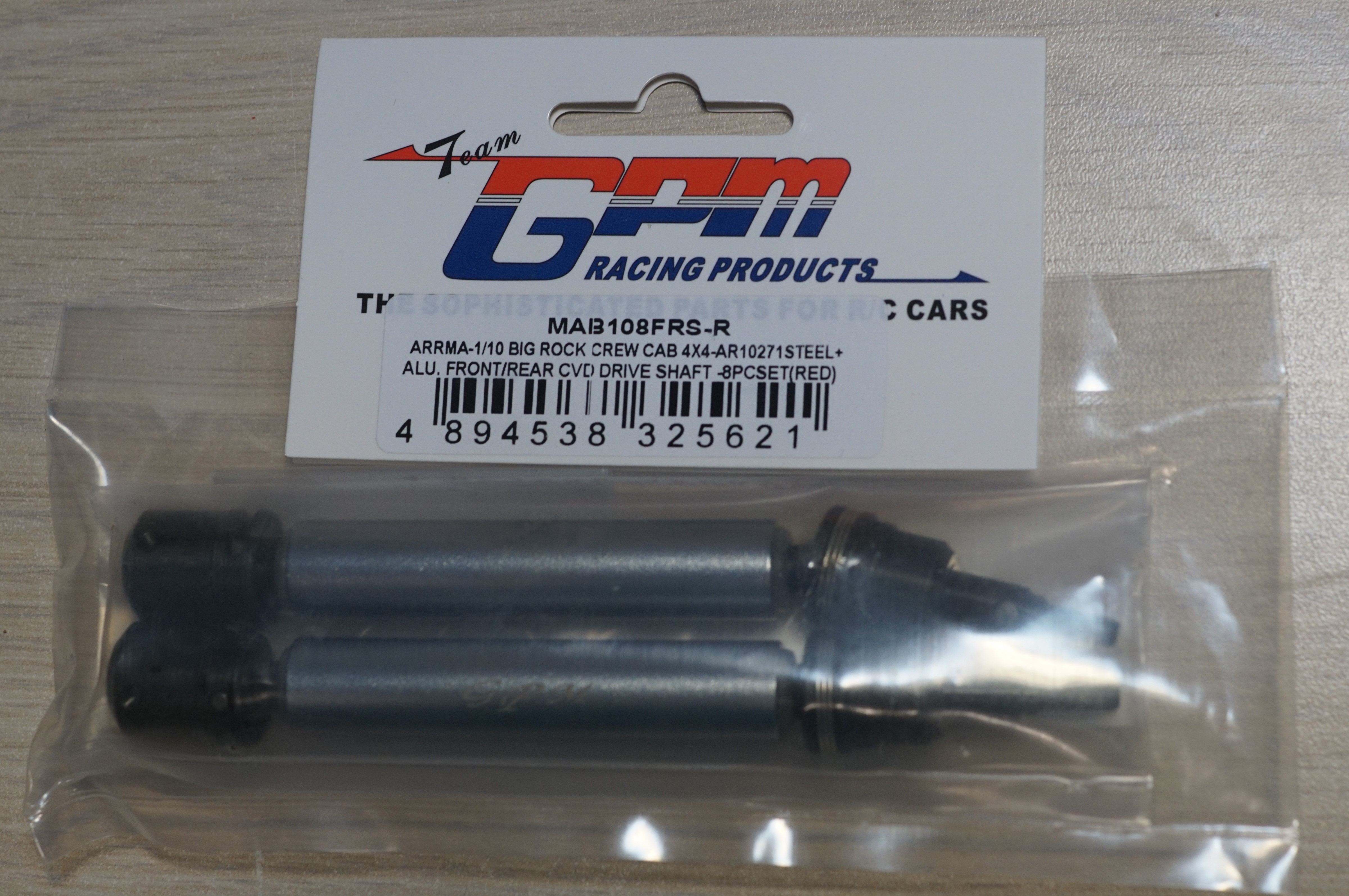
Big Rock GPMRacing - Wheel Driveshafts
- Thread starter xertian
- Start date
-
- Tags
- big rock cvd drive train granite
This site may earn a commission from merchant affiliate
links, including eBay, Amazon, and others.
links, including eBay, Amazon, and others.
- Thread starter
- #42
I don't have permission to view your album...
I don't see any method to share the album. Tried in Firefox and IE.
jondilly1974
Speed running apprentice, motor Slayer 🤘
Lifetime Premium!
Premium Member
Excellence Award
Build Thread Contributor
- Messages
- 26,134
- Reaction score
- 38,839
- Location
- Toledo, OH
- Arrma RC's
- Granite
- Infraction
- Kraton 6s
- Kraton EXB
- Senton 3s
- Typhon 6s
- Typhon 3s
You can just post them in this thread.I don't see any method to share the album. Tried in Firefox and IE.
- Thread starter
- #44


In case anyone was curious about album perms.

https://xenforo.com/community/threads/change-album-privacy-settings.144697/
jondilly1974
Speed running apprentice, motor Slayer 🤘
Lifetime Premium!
Premium Member
Excellence Award
Build Thread Contributor
- Messages
- 26,134
- Reaction score
- 38,839
- Location
- Toledo, OH
- Arrma RC's
- Granite
- Infraction
- Kraton 6s
- Kraton EXB
- Senton 3s
- Typhon 6s
- Typhon 3s
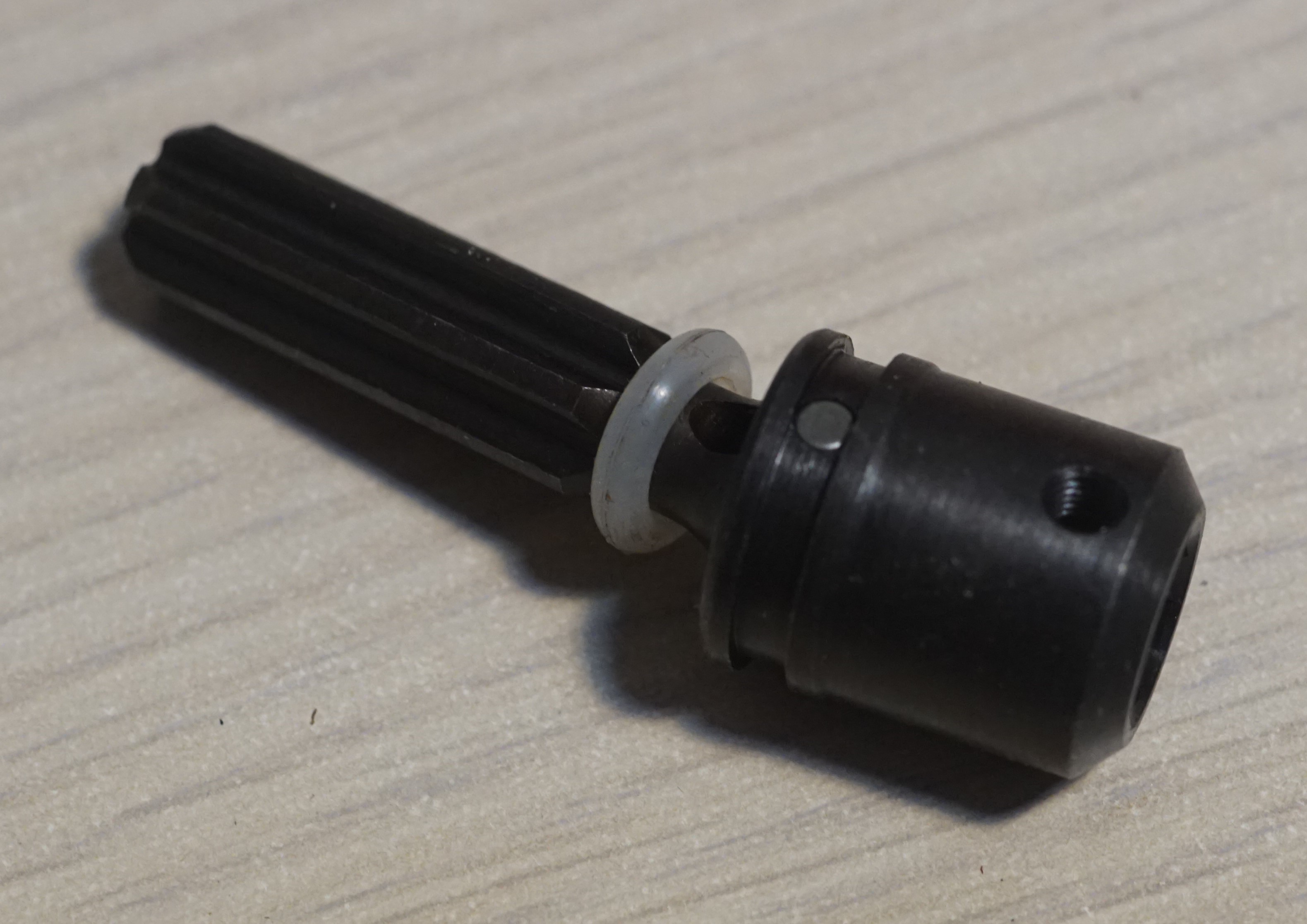
The grub screw is to hold the inside part of the shaft on to the diff output shaft.I snapped a few pics and dropped them in an album for those interested. I'm not certain how this forum software manages media so I apologize in advance if they are ridiculously huge. My first impressions are that these things look pretty beefy. Only the slider is aluminum and it shows on the scale. There are no spares included and I'm not certain why there is a grub/set screw in addition to the normal flat head screw that goes into the end of the output shaft. I may get these installed tonight but a test run is not going to happen.
View album 16
Done. If I understood your comments correctly, I think the results are better than initially expected. There are splines where there should be splines.How they hold up is obviously the next big question.
AimlessRC
Active Member
- Messages
- 189
- Reaction score
- 212
- Arrma RC's
- Granite
Well, first off I already like how they use the metal rings to hold the pins in place.
Secondly, I don't like those white o-rings... what are they expecting these to do, act as a bump stop under full compression? Maybe the center section "floats"... on the HR version the inner splines are pinned to the outer shaft so only the outside joint telescopes. Seems both sides of this telescope?
I'd like to see boots on these too... I have a spare set of Hot Racing boots that I'll see if they fit once mine come in.
Post up pics installed!
jondilly1974
Speed running apprentice, motor Slayer 🤘
Lifetime Premium!
Premium Member
Excellence Award
Build Thread Contributor
- Messages
- 26,134
- Reaction score
- 38,839
- Location
- Toledo, OH
- Arrma RC's
- Granite
- Infraction
- Kraton 6s
- Kraton EXB
- Senton 3s
- Typhon 6s
- Typhon 3s
O rings are to stop the aluminum from scratching the black metal I would guess.Well, first off I already like how they use the metal rings to hold the pins in place.
Secondly, I don't like those white o-rings... what are they expecting these to do, act as a bump stop under full compression?
I'd like to see boots on these too... I have a spare set of Hot Racing boots that I'll see if they fit once mine come in.
Post up pics installed!
- Thread starter
- #48
Something may not be clear in the pictures. These attach exactly like the factory shafts to the diff output with a screw in the end.The grub screw is to hold the inside part of the shaft on to the diff output shaft.
AimlessRC
Active Member
- Messages
- 189
- Reaction score
- 212
- Arrma RC's
- Granite
Maybe... I was hoping they weren't treating them as a sort of dust boot, or grease retention.O rings are to stop the aluminum from scratching the black metal I would guess.
Do the instructions (if any) mention installing with grease or lube of any kind?
Does the aluminum have a threaded hole in it anywhere? Could it be used to lock our one side or the other from telescoping?Something may not be clear in the pictures. These attach exactly like the factory shafts to the diff output with a screw in the end.
- Thread starter
- #50
The rubbers keep the sliding shaft from falling or rising more than needed as it is floating on both ends, unlike the stock step up that only floats at one end. I don't expect them to be a problem.
The aluminum slider is solid with no holes.
No instructions included.
The aluminum slider is solid with no holes.
No instructions included.
jondilly1974
Speed running apprentice, motor Slayer 🤘
Lifetime Premium!
Premium Member
Excellence Award
Build Thread Contributor
- Messages
- 26,134
- Reaction score
- 38,839
- Location
- Toledo, OH
- Arrma RC's
- Granite
- Infraction
- Kraton 6s
- Kraton EXB
- Senton 3s
- Typhon 6s
- Typhon 3s
What is this hole for then?Something may not be clear in the pictures. These attach exactly like the factory shafts to the diff output with a screw in the end.
- Thread starter
- #52
I think this setup calls for lube. IMHO
I'm not questioning where it goes, just why is is necessary given the factory screw method is used as well.
jondilly1974
Speed running apprentice, motor Slayer 🤘
Lifetime Premium!
Premium Member
Excellence Award
Build Thread Contributor
- Messages
- 26,134
- Reaction score
- 38,839
- Location
- Toledo, OH
- Arrma RC's
- Granite
- Infraction
- Kraton 6s
- Kraton EXB
- Senton 3s
- Typhon 6s
- Typhon 3s
That I can’t tell you. I didn’t know it had the inner screw for the diff output too. Hard to see that in the pics.I think this setup calls for lube. IMHO
I'm not questioning where it goes, just why is is necessary given the factory screw method is used as well.
bicketybam
Back from vacation!
Lifetime Premium!
Premium Member
Excellence Award
Build Thread Contributor
- Messages
- 13,394
- Reaction score
- 23,196
- Location
- New Milford, CT
- Arrma RC's
- BigRock 4x4
- Granite
- Infraction
- Kraton 8S
- Kraton 6s
- Kraton 4s
- Mojave
- Notorious
- Talion
- Typhon 6s
Is the splined part plastic?
jondilly1974
Speed running apprentice, motor Slayer 🤘
Lifetime Premium!
Premium Member
Excellence Award
Build Thread Contributor
- Messages
- 26,134
- Reaction score
- 38,839
- Location
- Toledo, OH
- Arrma RC's
- Granite
- Infraction
- Kraton 6s
- Kraton EXB
- Senton 3s
- Typhon 6s
- Typhon 3s
I honestly don’t see the inner screw in any of the pics you posted. Are you sure it’s in there?


AimlessRC
Active Member
- Messages
- 189
- Reaction score
- 212
- Arrma RC's
- Granite
They look metal... could it be used instead of the center screw? That way you wouldn't have to completely disassemble the joint to remove the axle bolt in the center of the out drive. Maybe you could file or drill a dimple in the out drive splines to recess the set screw.
Not saying you should... just wondering if this inner spline coupler is used in multiple kits with that as an option.
It comes with the screws...

Not saying you should... just wondering if this inner spline coupler is used in multiple kits with that as an option.
It comes with the screws...
- Thread starter
- #58
Maybe it's needed to prevent eveventual "wallering out" of the splines by keeping the splines locked.
Extra holding power is the easy answer that I'm going with. I'm not too excited about wrenching a fastener into the splines of my diff output shafts but we'll see how necessary and/or impactful it is.
Is the splined part plastic?
There's no plastic anywhere. the closest we get to plastic is the white rubber O rings you see that limit the slider's range of motion.
I honestly don’t see the inner screw in any of the pics you posted. Are you sure it’s in there?
Because of the captured pin setup these use the screws are not permanently part of the assembly the way they are with the stock units. The screws are in the bag as noted by AimlessRC. I'll grab a few more pics that hopefully clear that up.
I was having lighting challenges when taking those pics last night. ??
- Thread starter
- #59
Here are a few more pics that should clear up the diff attachment questions. The wheel side is identical as far as the joints are concerned.


- Thread starter
- #60
One of the rears is installed, no drama involved. I used purple loctite on the threads, a micro flat blade screw driver to push the split ring on, and some full fat automotive bearing grease on the slider splines. Everything looks good to me with no red flags thus far.
EDIT: I've since reinstalled this side and properly aligned the GPM set screw with the dimple in the output shaft.
I hope to be able to get back to wrenching tonight and test tomorrow.
EDIT: I've since reinstalled this side and properly aligned the GPM set screw with the dimple in the output shaft.
I hope to be able to get back to wrenching tonight and test tomorrow.


Last edited: