JDowns Limitless Build

This site may earn a commission from merchant affiliate
links, including eBay, Amazon, and others.

JDowns

Active Member
Messages
169
Reaction score
566
Location
Phoenix, AZ
Arrma RC's
  1. Infraction
  2. Kraton 6s
I figured I'd document this build as it goes along. I couldn't resist another custom project after going into my LHS to order a 8S Kraton, so I walked out with a Limitless roller.

Going with another Castle Monster X / 2200 since I want to pull telemetry off of this build as well.

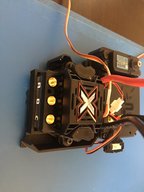
Custom ESC tray fitted into the existing ESC mount. Really like these threaded inserts from Penn Engineering. The existing (4) holes under the existing tray are used to mount the custom tray.

IMG_2298.JPG


Added a mount for the power switch and had a left-over Savox for the servo.
IMG_2305.JPG


Needed 12VDC for some accessories that will be added, so fitted a small 3S battery holder that gets clamped to the tower to tower brace.

IMG_2303.JPG


Custom mount for a pair of Yeah Racing 30x30mm fans.

IMG_2301.JPG


After some wear and tear I'll end up upgrading the bearing to Fast Eddy and at the same time the diff housing to Hot Racing. While all that is apart I have an extra set of Titanium turnbuckles from Lunsford Racing. But for the most part the internals of this will stay stock.
 

Attachments

  • IMG_2300.JPG
    IMG_2300.JPG
    245.7 KB · Views: 44
You have some the best work I've seen out there. Awesome. Love the attention to detail.:love: I'm following you. I will soon build my Lim. roller. I promised a video to all.
 
I really like the brass pem inserts in the 3D printed parts. I wonder if they are epoxied in or if they heat them and melt them in place?
 
I really like the brass pem inserts in the 3D printed parts. I wonder if they are epoxied in or if they heat them and melt them in place?

They are just pressed or tapped into place. I make the holes slightly smaller then tap into place with a Phillips screw driver. The fittings are tapered so when you screw into them they expand outwards digging into the plastic. If I need them flush mounted then I'll use a soldering iron and lightly press them flush.
 
They are just pressed or tapped into place. I make the holes slightly smaller then tap into place with a Phillips screw driver. The fittings are tapered so when you screw into them they expand outwards digging into the plastic. If I need them flush mounted then I'll use a soldering iron and lightly press them flush.
Awesome! It seemed like you were saying they were manufactured parts. I didn’t realize you were making these yourself. Very nice work. ??
 
This is going to be a lengthy process for sure with a lot of body work.

Front end is mocked up. Active headlights, and three OLED screens for telemetry data. Center screen for speed and rpm's. Right and left for ESC Temp and Motor Temp.

IMG_2321.JPG


IMG_2322.JPG


Cockpit is mocked up. The driver is a short Italian with a big head. :D

IMG_2323.JPG


Still need to do the wide body for the rear, F1 style engine intake behind the driver that will house the FPV camera system, black-box for the micro-controller, rear brake lights, and side skirts. I forsee a lot of sanding and bondo in my future.
 
Incredible. The details are unbelievable. You are a true hobbiest and craftsman. Not sure which I'm more impressed with. Yours or @LibertyMKiii's. Both outstanding works of art and engineering. ???
 
Very nice build. Excited to see how you implement the data screens.
@JDowns what sort of adhesive do you use on the body plastics to the 3D printed parts?

Gorilla Weld. Two part resin and hardener seems to work the best as it sets up pretty quick and is easy to sand. JB Weld plastic bond also works but is a bit trickier to set up and is more runny.

The screens are on the front end. I'll try and get a better picture. One in the center and one on each side wing. The camera will be in the air intake above the driver's head (think F1 style). There is black box in the rear of the vehicle with a Cortex M4 and the brake lights. I'll put the Castle Serial Link in the receiver box to intercept the telemetry data. An I2C multiplexer in the nose for the screens.

IMG_2325.JPG


Drivers pod starting to take shape.

IMG_2326.JPG


I test setup where the camera will go and it captures the steering wheel pretty nicely, so I may have to add a servo down there and have the steering wheel turn with the wheels. Might be a nice touch in the FPV.
Very nice build. Excited to see how you implement the data screens.
@JDowns what sort of adhesive do you use on the body plastics to the 3D printed parts?

If I would have gone with a traditional PETG rather than Ultimaker's CPE+ then I think Weldon 16 would actually bond the Lexan to the PETG rather nicely. The polymers in Ultimaker's CPE and CPE+ doesn't take all to Weldon like normal PETG's.
 
Last edited:
Gorilla Weld. Two part resin and hardener seems to work the best as it sets up pretty quick and is easy to sand. JB Weld plastic bond also works but is a bit trickier to set up and is more runny.

The screens are on the front end. I'll try and get a better picture. One in the center and one on each side wing. The camera will be in the air intake above the driver's head (think F1 style). There is black box in the rear of the vehicle with a Cortex M4 and the brake lights. I'll put the Castle Serial Link in the receiver box to intercept the telemetry data. An I2C multiplexer in the nose for the screens.

Drivers pod starting to take shape.

I test setup where the camera will go and it captures the steering wheel pretty nicely, so I may have to add a servo down there and have the steering wheel turn with the wheels. Might be a nice touch in the FPV.

That would be great with maybe some drivers gloves and arms visible?
Can't wait to see it all in a FPV video.

Probably not necessary and you have already come up with something, but you could add lights in this way to be more F1 like:
F1 replica.JPG

taillight Capture.JPG
 
Mario was fired yesterday. Decided to put the cam in the helmet of the driver. Wasn't liking the view from the air intake.

IMG_2333.JPG


Helmet is three pieces. Helmet, inside body out of TPU to mount the camera, and a TPU ring that holds a glass lens from a mini mag light.

Screen Shot 2019-12-05 at 7.54.30 AM.png
 
Old Thread: Hello . There have been no replies in this thread for 90 days.
Content in this thread may no longer be relevant.
Perhaps it would be better to start a new thread instead.
Back
Top