NeverDun
Member
- Messages
- 71
- Reaction score
- 143
- Arrma RC's
- Kraton 6s
I searched 4 wheel steering on this forum awhile back, and didn't really come up with anything besides people saying "Why bother, it's just more stuff to break". I agree. But idea just wouldn't leave me alone.
I wanted to make this as simple as possible for anyone with basic tools to accomplish if they wanted to repeat what I did. This means use as much existing off the rack Arrma parts as possible. So I assembled all of my spare parts, and a number of others collected from kit breakers.
I tried a variety of different parts and configurations and came to the conclusion that the only reasonable way to do this without a significant re-design and multiple custom components, was to leave the suspension and steering geometry alone. Any switching out of lower hinge pin blocks in an attempt to retain the locking features that mate with the chassis resulted in terrible bump steer characteristics.
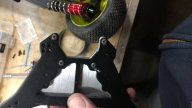
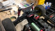
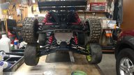
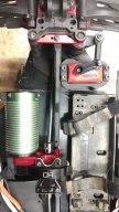
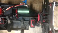
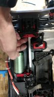
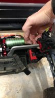
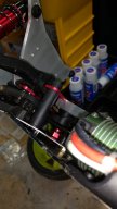
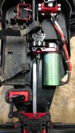
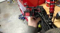
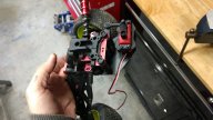
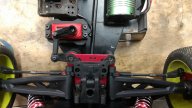
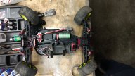
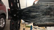
The only acceptable results came from literally taking the front end as a whole and sticking it on the back. It's surprisingly easy to do with very few permanent modifications to a couple of parts:
-Either the chassis or hinge pin plate (FF) need to be carefully notched out with a file to lock into one another.
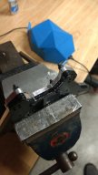
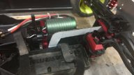
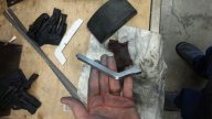
-The rear droop tabs need to be cut at an angle to fit in the arm pockets. I used a Dremel with a fiber reinforced cutting wheel for this.
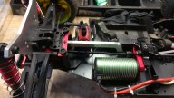
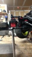
-Front shocks and shock tower need to be used unless you make a custom rear tower. At least with the Kraton, you can't drill holes in the rear shock tower for the upper hinge pins. The holes partially interfere with the existing tie rod holes.
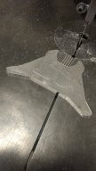
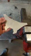
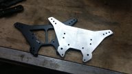
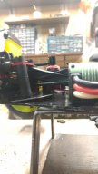
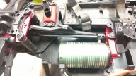
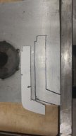
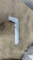
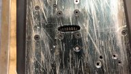
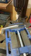
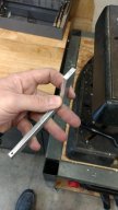
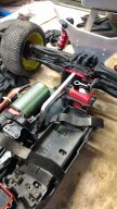
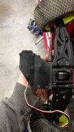
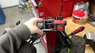
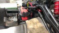
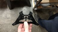
-A plate mimicking the front of the chassis is needed to brace the pick up points for the steering posts, and servo mount. The rear of the chassis is narrower than the front, and the servo would hang off of the side without a plate. The rear has no kick-up, so everything is angled upwards towards the center diff. The plate can be easily made by using a transfer punch through the existing mounting points at the front of the chassis on to sheet metal, and tracing the general shape. Then bend the opposite angle (making the servo mounting surface parallel to the chassis) and cut away excess material to lighten it up.
I drilled one hole on center and bolted through the horizontal section of the adapter plate (next to the servo) with a spacer (a nut) between the nut and the chassis to keep the plate stiff and level.
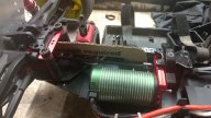
-The rear chassis brace will have to be custom. I found no simple solution for the original rear brace. Some custom solution will be necessary.
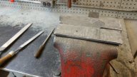
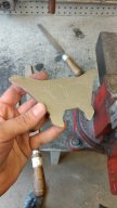
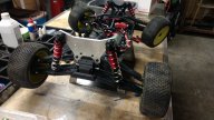
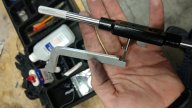
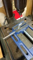
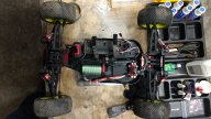
I am almost finished, except for the rear shock tower and rear brace. For the rear shock tower I have concluded I will just have to make my own, which is easy to do with a transfer punch and some aluminum plate.
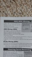
I am currently waiting on a Futaba 3PV to arrive with servo mixing so I can actually hook everything up and start playing with it. In my mind, the ideal situation would be to still have steering authority under full acceleration even with the front wheels off the ground. Of course there are a variety of other fun things you can do in the air, and with crabbing and such. This may be one of those things that just works better with an air transmitter, so you can do anything you want any time you feel like it ?.
I wanted to make this as simple as possible for anyone with basic tools to accomplish if they wanted to repeat what I did. This means use as much existing off the rack Arrma parts as possible. So I assembled all of my spare parts, and a number of others collected from kit breakers.
I tried a variety of different parts and configurations and came to the conclusion that the only reasonable way to do this without a significant re-design and multiple custom components, was to leave the suspension and steering geometry alone. Any switching out of lower hinge pin blocks in an attempt to retain the locking features that mate with the chassis resulted in terrible bump steer characteristics.
The only acceptable results came from literally taking the front end as a whole and sticking it on the back. It's surprisingly easy to do with very few permanent modifications to a couple of parts:
-Either the chassis or hinge pin plate (FF) need to be carefully notched out with a file to lock into one another.
-The rear droop tabs need to be cut at an angle to fit in the arm pockets. I used a Dremel with a fiber reinforced cutting wheel for this.
-Front shocks and shock tower need to be used unless you make a custom rear tower. At least with the Kraton, you can't drill holes in the rear shock tower for the upper hinge pins. The holes partially interfere with the existing tie rod holes.
-A plate mimicking the front of the chassis is needed to brace the pick up points for the steering posts, and servo mount. The rear of the chassis is narrower than the front, and the servo would hang off of the side without a plate. The rear has no kick-up, so everything is angled upwards towards the center diff. The plate can be easily made by using a transfer punch through the existing mounting points at the front of the chassis on to sheet metal, and tracing the general shape. Then bend the opposite angle (making the servo mounting surface parallel to the chassis) and cut away excess material to lighten it up.
I drilled one hole on center and bolted through the horizontal section of the adapter plate (next to the servo) with a spacer (a nut) between the nut and the chassis to keep the plate stiff and level.
-The rear chassis brace will have to be custom. I found no simple solution for the original rear brace. Some custom solution will be necessary.
I am almost finished, except for the rear shock tower and rear brace. For the rear shock tower I have concluded I will just have to make my own, which is easy to do with a transfer punch and some aluminum plate.
I am currently waiting on a Futaba 3PV to arrive with servo mixing so I can actually hook everything up and start playing with it. In my mind, the ideal situation would be to still have steering authority under full acceleration even with the front wheels off the ground. Of course there are a variety of other fun things you can do in the air, and with crabbing and such. This may be one of those things that just works better with an air transmitter, so you can do anything you want any time you feel like it ?.
Attachments
-
 IMG_20200222_163110443.jpg260.6 KB · Views: 122
 -
 IMG_20200222_163156304.jpg211.1 KB · Views: 74
 -
 IMG_20200222_163220126.jpg227.9 KB · Views: 69
 -
 IMG_20200222_163228325.jpg187.1 KB · Views: 90
 -
 IMG_20200222_202305704.jpg282.8 KB · Views: 84
 -
 IMG_20200222_202325291.jpg233.9 KB · Views: 83
 -
 IMG_20200222_202340102.jpg242.2 KB · Views: 79
 -
 IMG_20200222_202416064.jpg210 KB · Views: 84
 -
 IMG_20200222_202428579.jpg267.2 KB · Views: 83
 -
 IMG_20200222_202631399.jpg274.6 KB · Views: 90
 -
 IMG_20200222_202953654.jpg172.6 KB · Views: 75
Last edited:
")