Kraton Suchtragedy's Kraton EXB Build

What motor/pinion should I try first?

  • Arrma 4074 (2050kv + 16T pinion)

    Votes: 3 50.0%
  • Redcat 4690 (1050kv, 8mm shaft + 25T pinion)

    Votes: 3 50.0%

  • Total voters
    6
  • Poll closed .
This site may earn a commission from merchant affiliate
links, including eBay, Amazon, and others.

suchtragedy

(┛ಠ_ಠ)┛彡ɯɹɐ loɹʇuoɔ ǝʞoɹq
Premium Member
Build Thread Contributor
Messages
1,755
Reaction score
3,176
Location
Wenatchee, WA
Arrma RC's
  1. 4x4-Mega
  2. BigRock 4x4
  3. Felony
  4. Granite
  5. Infraction
  6. Limitless
  7. Kraton 6s
  8. Outcast 4s
  9. Typhon 3s
  10. Voltage
Finally got my day 1 pre-order from Horizon after it was 2.5 weeks late from the date they said it was shipping. The size of this thing in pics is deceiving, seems way bigger IRL.
20200804_152659.jpg


First things first is to drain the diffs and verify the rear diff shim situation and remedy if needed, then add new diff oil (50k/200k/25k)
20200804_160845.jpg


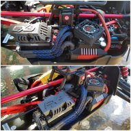
For electronics it will be getting the following:
  • Hex6 (160A, 6s version) ESC with a 40mm Wild Turbo Fans (WTF) high CFM fan retrofit
  • DS3235SG 35kg servo
  • DumboRC X6 radio with 6 channel gyro receiver
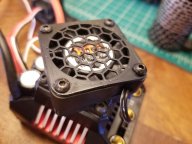
  • 2 x 30mm PowerHobby high CFM motor fans and heatsink

For motors I got two options so I will leave up a poll to help me decide...
  • Option#1: Arrma 4074 (2050kv) + 16T pinion (calculated top speed: 76mph @ 6s)
  • Option#2: Redcat 4690 (1050kv, 8mm shaft!) + 25T pinion (calculated top speed: 61mph @ 6s)

20200804_181033.jpg


The 4074 arrma motor is a motor I know so I think pairing it with a 16mm pinion with the dual fan+heatsink combo should be decent. However, I picked up this Redcat 1/5 scale 4690 motor on clearance and want to give it a try. It's got a pretty low kv (1050kv) which is half the rpm as the Arrma 4074, but I think it will be a torque monster. Pairing it with a huge 25T pinion it should still make decent speed (60mph ish).

I've test fitted both and with some modifications to the motor mount (center bored out to 17mm to allow fitment over the huge pinion, and motor slider trimmed slightly) the 4690 fits like a glove and it has almost no gap between it and the chassis, this meaning it's heavy weight won't be putting vertical strain on the motor mount.

InShot_20200804_182533979.jpg


Anyways more pics to come as I progress.
 

Attachments

  • 20200804_181050.jpg
    20200804_181050.jpg
    206 KB · Views: 39
Last edited:
I say the 2050kv but I’m interested in how the 1050kv would be. I would probably gear it up higher than 61mph tho. You won’t have the same air control.
 
I say the 2050kv but I’m interested in how the 1050kv would be. I would probably gear it up higher than 61mph tho. You won’t have the same air control.
Yeah I can go bigger if needed would just need to shave more off the mount if I still want to use both slide retainer screws. This motor is in a weird spot KV wise to where I don't have any real reference point on what to expect from it.

I'd go with the Arrma motor only because I don't know Jack about the other.
I have a second motor mount slider piece to attach to the 2nd motor so I can swap between the two easily. I probably will dial in the EXB with the Arrma motor first and then try the 4690 Can-o-Worms motor after and figure things out from there.
 
Stick that torque beast in there... you know you want to... it’s only a few minutes to swap out if you don’t like it ??. Plus, like you said, you “know” the arrma motor, sometimes it’s fun to get to know motors you don’t know already. :)

Nice OP btw, very good presentation ????
 
Day 2 Update:

Finished diff oil swap (50k/100k/25k) as well as adjusting the rear diff shims. I confirmed I had a little too much play and only had 0.7mm of shims per side. I added 1 x ARA709059 (0.2mm) shim to each side and everything seems to fits very nicely and dry test was good.

After the shims I started putting everything back together and that's when I noticed that the top of the shocks have a lot of play in them. The play is due to the plastic bushing used in the shock cap, it's in there very loose and actually falls right out once you remove the top shock mount. I decided to whip up a 3D printed TPU bushing and replaced the plastic bushing and now the shock is nice and snug fitting with zero play.

Next I mounted the servo which fit nicely and only needed to use the smaller of the 2 vertical spacers provided to just barely keep it from resting on the chassis.

20200805_182353.jpg


After the servo it was now time to figure out the best way to mount the Hex6 esc. I really wanted to mount the esc side to side with the power leads facing the middle and the motor wires facing the outside, however it put the esc only a few mm away from hitting the center diff outdrive cup. I didn't want to remove or cut up the side guard to push the esc away from the center so I abandoned the side to side mounting idea.

The alternative was to cut away the little edge at the rear of the stock esc mounting tray and install the esc front to back with motor wires facing the rear and power wires facing forward. Since I hate using zip ties, velcro, or double sided tape to secure an esc I took some measurements and designed a mounting plate that I could 3D print. It came out pretty well I think.
20200805_180040.jpg


20200805_180057.jpg


While I was printing the esc mount I started working on a way to mount the esc power button. I was able to adapt my push button power switch mount I designed for the Infraction receiver box lid and get it to mount onto the side of the roof support above the center diff.

20200805_174238.jpg


I just finished mounting the esc tray and roof support with my power button mount back into the truck and here's how it came out.

20200805_180123.jpg


Everything looks pretty clean so far. Next steps are to permanently mount whatever motor I decide to use and do some fancy wire braid and wire management and go from there.
 
Last edited:
Day 3/4 Update:

After thinking about it some more I decided to wait on trying the Redcat motor and so decided to go with the stock 6s arrma motor. I have a dual 30mm Power Hobby heatsink and fan I wanted to use but as always I gotta be "extra" and so I made this intake hood to keep debris from calling directly into the fans. I think it came out good and it kinda reminds me of a supercharger when it's installed.
20200807_162017.jpg


20200807_162145.jpg


Next came some soldering making 6.5mm bullets to 4mm bullets over 10awg wire, cleaning it up with some wire braid/heat shrink, and offset cut lengths so wire management would be clean and tight.

Got everything mounted and installed, mesh set, receiver/gyro, esc, and steering all calibrated, tires externally vented, wire mesh for fan wire loom, and zip ties where needed. Here's how it all came out.
20200807_161422.jpg


20200807_134135.jpg


20200807_134048.jpg


Next steps are to reinforce the body, and maybe design and print some LED light assemblies to give it a more aggressive look and added bling.
 

Attachments

  • 20200807_161422.jpg
    20200807_161422.jpg
    418.6 KB · Views: 32
Last edited:
Day 3/4 Update:

After thinking about it some more I decided to wait on trying the Redcat motor and so decided to go with the stock 6s arrma motor. I have a dual 30mm Power Hobby heatsink and fan I wanted to use but as always I gotta be "extra" and so I made this intake hood to keep debris from calling directly into the fans. I think it came out good and it kinda reminds me of a supercharger when it's installed.
View attachment 93365
View attachment 93364

Next came some soldering making 6.5mm bullets to 4mm bullets over 10awg wire, cleaning it up with some wire braid/heat shrink, and offset cut lengths so wire management would be clean and tight.

Got everything mounted and installed, mesh set, receiver/gyro, esc, and steering all calibrated, tires externally vented, wire mesh for fan wire loom, and zip ties where needed. Here's how it all came out.
View attachment 93366
View attachment 93367
View attachment 93368

Next steps are to reinforce the body, and maybe design and print some LED light assemblies to give it a more aggressive look and added bling.
Love the power button holder and the fan guard, very well done sir ????
 
Day 5/6 Update:

Before taking this thing out I felt it was probably a good idea to first reinforce the body. In the past I've used gorilla tape but this time I wanted to try something different. I've seen the drywall tape + shoe goo method a few times and wanted to try it, but rather than buying shoe goo I decided to give brushed on truck bed liner a try. After a day and a half of drying the body feels a lot less flimsy but still flexible and the bed liner definitely feels like it's going to hold up to abuse of dirt/rock/debris pelting the bottom side of the body as it's thrown by the tires.

InShot_20200809_144541498.jpg


Next was my attempt to install some LED lights. I've had a light set (2 white front headlights, 2 red rear tail lights) for a while not being used and wanted to give it a try. The lights are prewired as a harness all tied together to a single 3 pin connector. This makes it easy to install and connect to the transmitter, I plan on using Channel 3 on/off for simple operation.

When it came to mounting the lights I wanted to make it clean and not janky, also I didn't want to butcher the front bumper/body/wing assembly to fit the LEDs on/through them. After a day of messing with some ideas I came up with a 2 piece design for the front headlights. The 1st piece is a mounting plate that installs on the top of the EXB front bumper spring. The 2nd piece is a bar that secures to the plate via 3mm screws + locknuts positioned so the underside locknuts are in the middle of the 2 rings on the bumper spring. The bar then has 2 light buckets that go around and drop just below the front bumper, angled slightly down so they project on the ground better.

I had to design 2 bars in total with the V1 being first and having a simple straight bar and drop buckets but it didn't leave as much room behind the buckets as I wanted for wire clearance of the the front suspension arms as they traveled up/down. Next was the V2 which dropped at a forward angle giving the buckets about 5mm of additional clearance between the rear of the buckets and the arms.

InShot_20200809_145527099.jpg


I printed everything out of flexible 95A Ninjatek Cheetah TPU. After a test fit I will say that I am very pleased with the results. The best part is since it's made to be flexible there is zero worry about it impeding the function of the stock bumper nor any worry that it will get destroyed in bad crashes. Worst case scenario the lights pop out of the buckets.

20200809_144208.jpg


Next is coming up for a design for the rear lights and will share that once I figure out something I am happy with.
 
Last edited:
Day 5/6 Update:

Before taking this thing out I felt it was probably a good idea to first reinforce the body. In the past I've used gorilla tape but this time I wanted to try something different. I've seen the drywall tape + shoe goo method a few times and wanted to try it, but rather than buying shoe goo I decided to give brushed on truck bed liner a try. After a day and a half of drying the body feels a lot less flimsy but still flexible and the bed liner definitely feels like it's going to hold up to abuse of dirt/rock/debris pelting the bottom side of the body as it's thrown by the tires.

View attachment 93632

Next was my attempt to install some LED lights. I've had a light set (2 white front headlights, 2 red rear tail lights) for a while not being used and wanted to give it a try. The lights are prewired as a harness all tied together to a single 3 pin connector. This makes it easy to install and connect to the transmitter, I plan on using Channel 3 on/off for simple operation.

When it came to mounting the lights I wanted to make it clean and not janky, also I didn't want to butcher the front bumper/body/wing assembly to fit the LEDs on/through them. After a day of messing with some ideas I came up with a 2 piece design for the front headlights. The 1st piece is a mounting plate that installs on the top of the EXB front bumper spring. The 2nd piece is a bar that secures to the plate via 3mm screws + locknuts positioned so the underside locknuts are in the middle of the 2 rings on the bumper spring. The bar then has 2 light buckets that go around and drop just below the front bumper, angled slightly down so they project on the ground better.

I had to design 2 bars in total with the V1 being first and having a simple straight bar and drop buckets but it didn't leave as much room behind the buckets as I wanted for wire clearance of the the front suspension arms as they traveled up/down. Next was the V2 which dropped at a forward angle giving the buckets about 5mm of additional clearance between the rear of the buckets and the arms.

View attachment 93633

I printed everything out of flexible 95A Ninjatek Cheetah TPU. After a test fit I will say that I am very pleased with the results. The best part is since it's made to be flexible there is zero worry about it impeding the function of the stock bumper nor any worry that it will get destroyed in bad crashes. Worst case scenario the lights pop out of the buckets.

View attachment 93630

Next is coming up for a design for the rear lights and will share that once I figure out something I am happy with.
Shoegoe and dry wall tape pulls the paint of my 4s bodies even shoegoe alone does in a few spots idk if its differant on the 6s
 
Shoegoe and dry wall tape pulls the paint of my 4s bodies even shoegoe alone does in a few spots idk if its differant on the 6s
Good to know, guess we'll see. I'm not terribly worried about it as I mainly just want the body to not break and not so much the paint. Bonus of a black paint scheme is with black bed liner hopefully paint damage won't show as much.
 
Good to know, guess we'll see. I'm not terribly worried about it as I mainly just want the body to not break and not so much the paint. Bonus of a black paint scheme is with black bed liner hopefully paint damage won't show as much.
Well if the paint gets pullet off the shoe goo mod or tape over it will do nothing because the shoego and dry wall tape is not reinforcing that area anymore if you can reach the spot with more shoegoe again great
 
Well if the paint gets pullet off the shoe goo mod or tape over it will do nothing because the shoego and dry wall tape is not reinforcing that area anymore if you can reach the spot with more shoegoe again great
Even if some areas separate (which I doubt, I did a good job with a brush getting the liner into the mesh and contacting the body) the mesh and liner is all stuck together as 1 big shell and it's not going to rip apart. The main goal is to keep the body from cracking apart usually at bends/corners and edges. Nasty impacts and roof landings is going to chip paint but should not affect the integrity of the whole for the most part.

But like I said we'll see.
 
Had a question about your fan adapter. I had one printed (THANK YOU FOR THIS!), and didn't realize it was supposed to go over the existing shroud, so I used some stand offs to hold the mount over the caps. Now that I'm realizing you designed it to go over the existing shroud I think Ill try it that way.

My question is, do you cut the center out of the shroud or leave it stock?
I left it alone but I suppose you could cut it. Your call
 
Day 7 Update:

After messing with a few different ideas this is the best I could come up with for the rear lights. Again another 2 piece mount/light bar design with the mount making use of the rear pin retainer cover. Printed again out of TPU so it's rigid yet flexible.

20200810_123121.jpg


Dressed the wires in more of the wire braid and got it wires for on/off operation on channel 3. Tested last night and all works well and it looks great in the dark.

20200810_113519.jpg


I think I'm done with this truck for a little while, time to go break it in somewhere.
 
Back
Top