- Messages
- 6,083
- Reaction score
- 13,925
- Location
- UK..
- Arrma RC's
- Infraction
- Mojave EXB
- Outcast 8s
- Outcast EXB
- Talion EXB
- Typhon 6s
I have some ABEC-7 ceramic bearings on the way.
Mmmmmm nice..??

Follow along with the video below to see how to install our site as a web app on your home screen.
Note: This feature may not be available in some browsers.
I have some ABEC-7 ceramic bearings on the way.
The CFD software I have used so far is decent showing air flows, but that is about the extent of what it can do. I was looking for data on downforce distribution. Too much force in the rear could cause the front to lift etc... I spoke with a few companies about trial software and that appears to not be an option at this time. Autodesk CFD for example is a subscription for 1 year at $10k. Consultation companies charge around $2-4k. Wind tunnel time is outrageous.
SO it looks like I may build a scale wind tunnel in the garage with 4 sensing pads (1 for each wheel) to measure downforce, plus a 5th sensor in the rear measuring drag force. Based on some calculations it appears I can get wind speeds up around the 120-150mph range through a small test area. This may be my summer project.
Also it may provide some side money providing test simulations for other test projects at some to be determined fee.
-Liberty
I think I just dropped a few IQ points reading this?...but I did gain a headache....good stuffReally think so? (honestly interested in any thing that might help) I have a few of them.
Seems like they do not kick in or do anything until the car has some significant angle differing from the direction of travel. From my experience above 80mph once a car is sideways it is game over. The car takes flight and does more flips than the Olympics.
My thoughts are they are better suited for off-road use. My cars typically drive very straight if my alignments are good and throttle application is smooth. I am getting a bit shaky as I get older...
CFD images from design V2. Identifies a few areas that can be improved (orange), which had mostly to do with my laziness during the drawing. Testing at 67 meters per second (150mph)
Yes that means that 200mph is nearly a football field per second. CRAZY!
View attachment 38109
View attachment 38110
View attachment 38111
-Liberty
Is that a Transformer or the real thing..????
Ha thanks! This project is going to be a very slow one. This release of the Arrma Limitless is going to slow me down, since I just have to play with thing a little...This is craziness how much detail it takes to hit these insane speeds nowdays. Nice to see that you’re going with the dream build! I’ll be sitting on the edge of my seat until it’s done lol.
I originally looked at BOCA bearings, and I have used them before but the full set of orange seal ceramics were $200.00 usd@LibertyMKiii ... If you don't mind me asking, how much did those bearings set you back..??
I suspect with these findings that the diffuser and underbody on the Limitless/Infraction are most likely all cosmetic.
-Liberty
Citation: Mokhtar, W. and Lane, J., "Racecar Front Wing Aerodynamics," SAE Int. J. Passeng. Cars - Mech. Syst. 1(1):1392-1403, 2009, https://doi.org/10.4271/2008-01-2988.
")
Arrma Aerospace in the house! If you bring that body to fruition, you may just change the speed run game. What will you call it now that Limitless is taken?I have what I believe is a solid plan for the center driveshaft and motor mount setup now, which was one of the big hurdles left on my list before cutting out the chassis (carbon fiber)
I have decided to share my aerodynamic design since I highly doubt anyone is going to attempt "stealing" this concept.
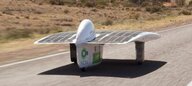
Despite some concerns mentioned in above post #30 I have decided to push on. To explain how I got here trying something different. The concept is used heavily in college solar car competitions. Concepts behind this design is to reduce drag and in their application you can see the curve on the top surface of the body (acting as an airfoil). This is used to create a neutral lift/downforce at their target speed which isn't very high due to the range of their race.
View attachment 41884
View attachment 41882
View attachment 41883
The above image does a good job of illustrating the drag behind a car that it has to "pull" in addition to its own aerodynamic frontal area.
Adapting this concept to my uses the side "pontoons" house the LiPo batteries between the front and back wheels on each side. I am undecided if I will use 4 LiPo batteries to mitigate voltage drop (weight is also an enemy and my LiPos are 2 lbs each). The center section is shaped like and inverted airfoil and utilizes the space between the center and the ground as a venturi. This is also known as ground effect, but not the application used in aircraft. The low pressure zone would effectively suck the car to the ground with less drag penalties than a standard wing on top of the vehicle would. This is very similar to a diffuser/splitter setup on cars but a much larger use of those concepts. This center section would also be what we typically see in a RC car where the ESC and motor will sit.
The side pontoons would also minimize wing tip effect also which is a plus
Now for the good stuff (It already looks fast right?):
View attachment 41876
Front:
View attachment 41877
Rear:
View attachment 41878
On CFD fast moving air starts with white then to orange and finally red. Blue is slower moving air.
Fast moving air creates low pressure zone where negative lift or what we call downforce from the venturi effect exists.
View attachment 41880
View attachment 41881
-Liberty
That is a good question and it is very likely I will make a custom body for the Limitless also...Arrma Aerospace in the house! If you bring that body to fruition, you may just change the speed run game. What will you call it now that Limitless is taken?
Have you considered using the dog bones from a different brand, possibly one geared more to racing? In fairness, the Limitless was designed to go fast, so I imagine that the parts included in the roller should be able to hold up. Food for thought then. Looking forward to seeing that body once the designs are final. That catamaran design seems ideal, but I just can't grasp how you would form it around and existing chassis. I leave the aerospace to you. I just like to break stuff ?Oddly enough @Notorious J I have had some issues with my 1/10 scale diffs along with concerns of the abilities of the dog bones holding the power I plan on using. Long story short this build is evolving into a Limitless build now. The exception is I wont be using the Limitless body or aero so it may not resemble the production Limitless very much beyond the guts on the inside. The plan is to make it the way I feel the Limitless should be (maybe a future view into the V2 Limitless?) Can't wait to get the Limitless and begin ripping it apart
Have you considered using the dog bones from a different brand, possibly one geared more to racing? In fairness, the Limitless was designed to go fast, so I imagine that the parts included in the roller should be able to hold up. Food for thought then. Looking forward to seeing that body once the designs are final. That catamaran design seems ideal, but I just can't grasp how you would form it around and existing chassis. I leave the aerospace to you. I just like to break stuff ?
Register and gain access to Discussions, Reviews, Tech Tips, How to Articles, and much more - on the largest Arrma RC community for RC enthusiasts that covers all aspects of the Arrma-RC brand!
Register Today It's free! This box will disappear once registered!