
Greengaunja
Ise da by' dat burns da Senton........
Premium Member
ArrmaForum Fan
Build Thread Contributor
- Messages
- 2,674
- Reaction score
- 4,561
- Location
- Durham Region, Ontario Canuckistan
- Arrma RC's
- Senton 6s
- Senton 3s
- Thread starter
- #21
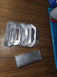
Scorched landed.
 Thought shipping would be faster but hell, who am I to complain? I ordered it late Thursday lol. Im just glad the front bracket is in so I can finalize my template in time for for the Wednesday delivery of my 400 ×300mm carbon fiber plate. Already I've decided to do a couple more tweaks to my custom 1/8th GT SWB chassis.
I've been debating whether or not that the two inches I've added to the width will be sufficient. Seriously wondering if I should add more. The thinking here is, if I overdo it I can always trim it back. But I can't add width. I also have this idea of using the Senton side skirts to hold the mid sections of the body in better than my last setup. This will be needed, especially if I'm pushing for 150mph. At least this way batteries will be fully inside chassis.


Secondly, I've been wondering about can sizes. Putting the center tower in line with the rear and front has the drawback of putting the motor closer to the rear differential input cup. And severely limits motor options. This is key because since I found out a PPS mount raises the motor more, allowing for a motor can larger than the HW 4985. I don't want to close that door should I need or want a larger motor. Although I'm expecting this build to be lighter than my EXB Senton 8s, the thought process behind the power train remains the same. Slow down acceleration to keep it planted and use that torque to slowly build up more speed down the stretch. However it was noted that I would likely have to trim some of the pinholder off and I knew there was a possibility I'd need to grind the input cup shorter. That's when it hit me, make the chassis slightly longer, just not long enough to lose its SWB status. So what I've done is, moved the center tower ahead 3mm and added 3mm to the front of chassis. The front dogbone will remain 116mm(subject to change slightly). The rear 82mm Senton shaft will be replaced with the 85mm Senton driveshaft. I foresee another Scorched order coming up due to my custom shaft guy being swamped at the moment.


I've been debating whether or not that the two inches I've added to the width will be sufficient. Seriously wondering if I should add more. The thinking here is, if I overdo it I can always trim it back. But I can't add width. I also have this idea of using the Senton side skirts to hold the mid sections of the body in better than my last setup. This will be needed, especially if I'm pushing for 150mph. At least this way batteries will be fully inside chassis.
Secondly, I've been wondering about can sizes. Putting the center tower in line with the rear and front has the drawback of putting the motor closer to the rear differential input cup. And severely limits motor options. This is key because since I found out a PPS mount raises the motor more, allowing for a motor can larger than the HW 4985. I don't want to close that door should I need or want a larger motor. Although I'm expecting this build to be lighter than my EXB Senton 8s, the thought process behind the power train remains the same. Slow down acceleration to keep it planted and use that torque to slowly build up more speed down the stretch. However it was noted that I would likely have to trim some of the pinholder off and I knew there was a possibility I'd need to grind the input cup shorter. That's when it hit me, make the chassis slightly longer, just not long enough to lose its SWB status. So what I've done is, moved the center tower ahead 3mm and added 3mm to the front of chassis. The front dogbone will remain 116mm(subject to change slightly). The rear 82mm Senton shaft will be replaced with the 85mm Senton driveshaft. I foresee another Scorched order coming up due to my custom shaft guy being swamped at the moment.
Last edited:


") Having to do this all by-hand doesn't look like fun.
Having to do this all by-hand doesn't look like fun.